Raspberry Pi Security Camera

Camera icon
After we were repeatedly struck by a thief who would steal a carton of milk from the weekly delivery of The Milkman, I decided to use a Raspberry Pi to install a basic camera to watch over our front porch. (Note: the milkman's business no longer exists. Too many milk thieves?)

Summary of features

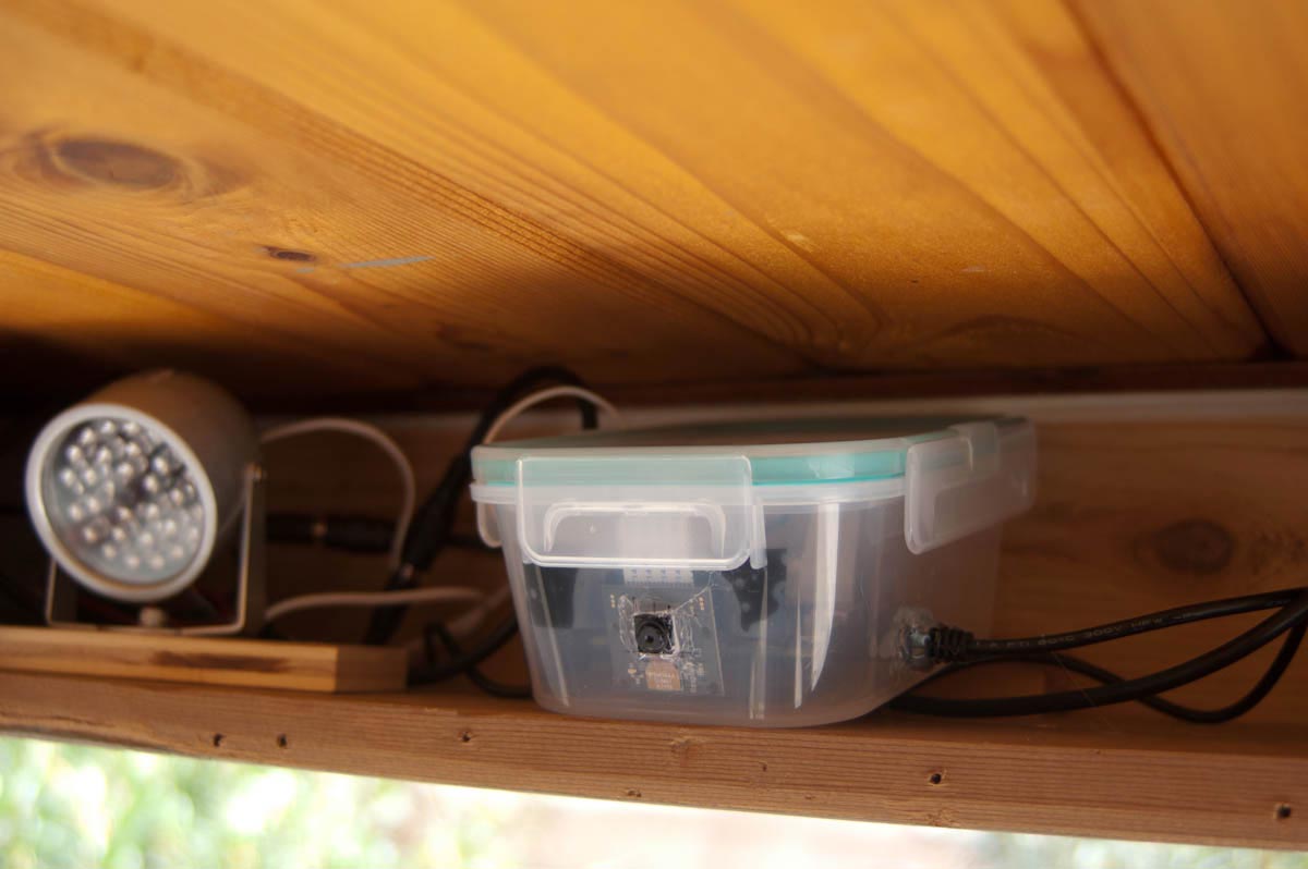
This Raspberry Pi camera runs "Motion", a software motion detector to capture high-quality images twice a second when something moves in the field of view. To increase sensitivity at night, I'm using a PiNoir camera, which doesn't have an infrared filter. When motion is detected, two arrays of infrared LEDs are switched on for the duration of the motion event. (LEDs are only turned on when it's dark and when motion is detected.) Images are sent wirelessly to a shared SMB drive on an old PC running Linux Mint, where a time-lapse mp4 movie is created automatically at the end of the day.

Images

RPi camera prototype
Prototype of the camera system on a breadboard.
RPi camera prototype: circuit detail
Detail of the optocoupler and TIP122 based switching circuit.
RPi camera prototype: circuit detail
A cheap plastic container houses the Raspberry Pi, with the camera peeking out through a whole in the front. The whole assembly is housed in a weather-protected nook I installed above the front porch.
RPi camera prototype: circuit detail
An electrical box houses the switch circuit. The cables dangling out from the front port provide 12V to the LEDs when the switch is on. There's also a logic input on the side that gets connected to a GPIO pin on the Raspberry Pi. This input side is electrically isolated from the 12V side with the help of an optocoupler.
Example image sequence: Bob the tail-less raccoon walks by the garage three minutes after I go inside, in the middle of a sunny afternoon in early March. Note: the video doesn't seem to be playing in Firefox.

Motion detection software

I installed "Motion" for the Raspberry Pi camera via the instructions on the UV4L site here: http://www.linux-projects.org/modules/sections/index.php?op=viewarticle&.... The maximum resolution I was able to get without weird things happening was 1280 x 1024 pixels, which gives plenty of detail for this purpose. "Motion" also includes a live webcam server, which is useful for checking who's at the door from upstairs without having to run down. I'm using a mask file to avoid triggering motion events from areas outside our property. All of these features are easy to install, and are described in detail elsewhere.

Python programs to switch lights on and off for a motion event

The installed "Motion" software includes the ability to call scripts at the beginning and end of motion events. I wrote two simple Python programs to communicate with "motion" and control the state of GPIO pins on the Raspberry Pi, which are used to switch on two IR LED arrays. One script is a TCP/IP server I called "eventResponderServer" that runs on the Raspberry Pi and waits for messages on a certain port. If that message is the word "on", the program switches a particular digital pin to HIGH; if the message says "off", it sets the pin to LOW. (If the message is "quit" the server program shuts itself off.) Another small Python program, the "eventResponderClient", is called when "Motion" determines an event has started or ended. It then sends the "on" or "off" messages to the port (on localhost) on which the eventResponderServer is listening. The commands called for a motion event can be set in the "/etc/motion/motion.conf" file by modifying the lines starting with "on_motion_start" and "on_motion_end":
/etc/motion/motion.conf excerpt
  1. # Command to be executed when an event starts. (default: none)
  2. # An event starts at first motion detected after a period of no motion defined by gap
  3. on_event_start /home/pi/bin/eventResponderClient.py on
  4.  
  5. # Command to be executed when an event ends after a period of no motion
  6. # (default: none). The period of no motion is defined by option gap.
  7. on_event_end /home/pi/bin/eventResponderClient.py off
Currently, only one GPIO pin is used to switch on IR lights. The program could be easily extended to switch more than one device, however. In order not to elicit a motion event when the lights are turned off again, the following parameters were adjusted in the motion config file: lightswitch: set to 40 minimum_motion_frames: set to 3 pre_capture: set to 3
/etc/motion/motion.conf excerpt
  1. # Ignore sudden massive light intensity changes given as a percentage of the picture
  2. # area that changed intensity. Valid range: 0 - 100 , default: 0 = disabled
  3. lightswitch 40
  4.  
  5.  
  6. # Picture frames must contain motion at least the specified number of frames
  7. # in a row before they are detected as true motion. At the default of 1, all
  8. # motion is detected. Valid range: 1 to thousands, recommended 1-5
  9. minimum_motion_frames 3
  10.  
  11. # Specifies the number of pre-captured (buffered) pictures from before motion
  12. # was detected that will be output at motion detection.
  13. # Recommended range: 0 to 5 (default: 0)
  14. # Do not use large values! Large values will cause Motion to skip video frames and
  15. # cause unsmooth mpegs. To smooth mpegs use larger values of post_capture instead.
  16. pre_capture 3

Python source code for "eventResponderClient.py" and "eventResponderServer.py"

The full code for the Python helper programs can be found on my BitBucket account here:

https://bitbucket.org/amphioxus/eventresponder/overview

Creating a daily movie with avconv

Instead of having "motion" create videos on the RPi, I'm using a shell script on a larger Linux box that runs every night to produce a time-lapse MP4 movie from the image sequence. The script uses a modified version of the Perl "rename" command that allows the use of an incremental counter. The renaming step changes the time-stamped file names coming from the camera into sorted file names with a zero-padded counter at the end, allowing "avconv" to create a correctly composed movie file from the image sequence. (The modified rename program can be found here: http://www.volkerschatz.com/unix/uware/rename.html. I called it "renum" on my system.)
Shell script
  1. #!/bin/sh
  2.  
  3. # Shell script to create a movie of security camera footage (front porch camera)
  4. # Needs a modified rename script from here: <a href="http://www.volkerschatz.com/unix/uware/rename.html
  5. #">http://www.volkerschatz.com/unix/uware/rename.html
  6. #</a> Armin Hinterwirth, 2014-2015
  7.  
  8. # Get current date and time to create file name:
  9. TIMESTAMP=$(date +"%Y-%m-%dT%H-%M-%S")
  10. FILE="daily_movie_frontcam.${TIMESTAMP}.mp4"
  11. # Specify directories:
  12. ARCHIVEDIR="/home/armin/Videos/security_cameras/front_porch_cam/"
  13. TARGETDIR="/home/raspi/cam_upload"
  14. LOGFILE="/tmp/mysecam.log"
  15.  
  16. # Start the action...
  17. # Switch to directory supplied as first argument:
  18. cd $TARGETDIR
  19. # Spit out some debugging info:
  20. echo "-----------------------------------------------------" >> $LOGFILE
  21. echo "Date start: $(date)" >> $LOGFILE
  22. echo "Creating nightly time-lapse movie from image sequence" >> $LOGFILE
  23.  
  24. # Rename files
  25. renum -v 's/(\d+)-(\d+)-(\d+)/sprintf("image_%05d",${i})/e' *.jpg
  26. echo "Renamed jpg files" >> $LOGFILE
  27.  
  28. # Create movie from images
  29. { avconv -r 24 -i image_%05d.jpg -b:v 2080k -r 24 $FILE; } 2>>/tmp/avconv_error.log
  30. MOVIECREATED=$?
  31. # Check whether last command returned a zero (i.e. succeeded). Only then, proceed:
  32. if [ $MOVIECREATED -eq 0 ]; then
  33. echo "Created mp4 movie file" >> $LOGFILE
  34. # Move new movie file to permanent location:
  35. mv $FILE $ARCHIVEDIR
  36. echo "Moved file ${FILE} to archive directory: ${ARCHIVEDIR}" >> $LOGFILE
  37. echo "Nightly time-lapse movie created successfully" >> $LOGFILE
  38. # Delete image files when done (using find in case argument list is too long for simple rm)
  39. find . -name "image_*.jpg" -print0 | xargs -0 rm
  40. # echo "Image files deleted."
  41. else
  42. echo "Movie creation failed. $(date)" >> $LOGFILE
  43. fi
  44. echo "Done: $(date)" >> $LOGFILE

Switch circuit

Lights obviously draw too much current to be powered directly by the Raspberry Pi's GPIO pins. Therefore, I'm using an opto-coupled transistor switch circuit to protect the RPi, and switch the LED arrays running off a 12V supply. Here is a schematic of the circuit:
Schematic of the opto-coupled circuit used to switch the LED arrays from the Raspberry Pi's I/O pins. NOTE: "Dror" discovered that there's an error in the schematic: as shown the LEDs connected to the header would always be on. JP1 on the header should not go to GND, but to the TIP122 transistor.

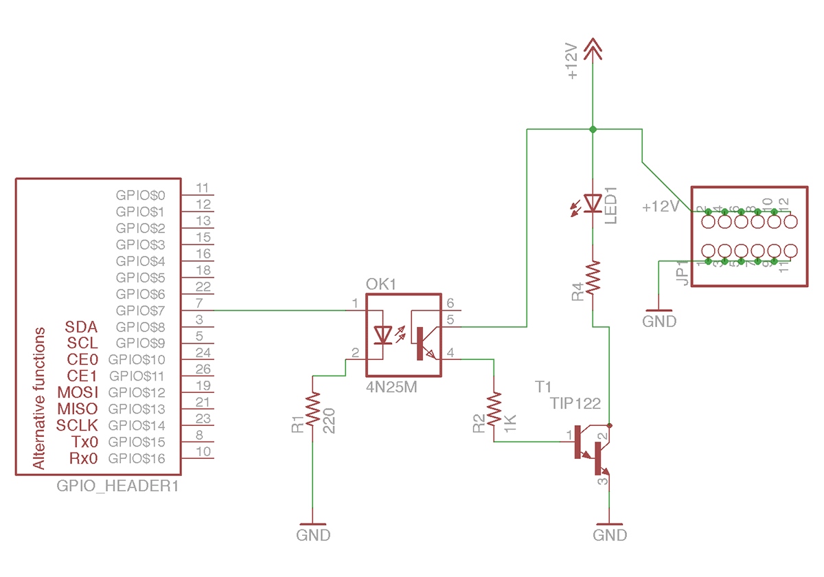
The switch circuit uses a 4N25 optocoupler to electrically isolate the Raspberry Pi from the rest of the circuit. A TIP122 found in my box of random electronics parts does the switching. LED1 is an indicator that lights up during a motion event. (R4 is a 1.5K Ohm resistor.) To the right of the image is a header, to which the LED arrays are attached.

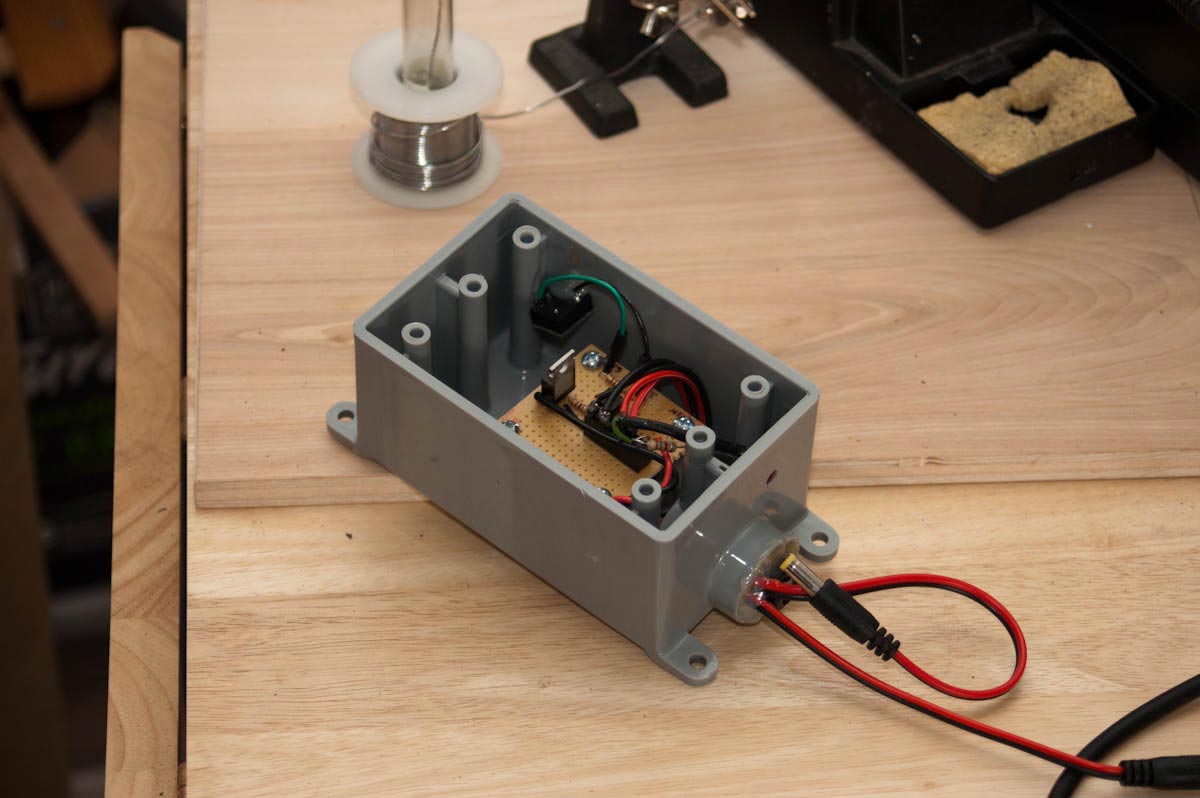
I placed the small breadboard in a weather-tight plastic box (see picture in gallery below) to protect it a bit more than the wood enclosure I built underneath our porch already does.

Parts list

Here's a list of the more important parts used for my camera system:

  • Raspberry Pi, model B+
  • PiNoir camera
  • Edimax wireless dongle: http://amzn.com/B003MTTJOY
  • CMVision IR30 WideAngle IR Illuminator http://amzn.com/B001P2E4U4
  • 2N24 optocoupler that I bought a long time ago from Jameco
  • TIP122 transistor, various resistors, low-power LED
Category: 
Making Stuff
Photos / Video
Code

Comments

You write that the IR led array is connected to the header. It will be always ON as it gets 12V all the time.
According to the schematic the optocoupler only switches on the LED1 indicator.

I haven't checked comments in a while, so I missed yours. You're right, the schematic for the LED array is wrong! Thanks for catching the error. JP1 of the LED array shouldn't just go to ground. It goes to (2) on the switching transistor, just like the indicator LED. (The load is low enough for the small panels that the TIP122 can switch all of them.)